Finite Element Analysis (FEA)
Finite Element Analysis (FEA)
Our team has delivered more than 115 assignments that involved FEA analysis. With multiple ANSYS licenses, we ensure a quick turnaround time. Our experience includes all varieties of structural simulations possible like inertial, modal, random vibration, thermal stresses, drop, transient shock and fatigue. We regularly handle all kinds of non-linearities, be it material, geometrical or contact based. We use all our experience for the appropriate idealization of structures for optimal finite element models.
Our Expertise
- Linear and non-linear FEA analysis, modal analysis and mode shapes
- Impact, Shock and Vibration analysis
- Transient and thermal analysis
- Static and Dynamic analysis, multi-body dynamics
- Aeroelastic analysis, fatigue, creep, fluid-structure interaction (FSI)
Where we Serve
- Aerospace and defence for design and design approval
- Heavy engineering design and development
- Design of impellers, pipes, valves in the fluid machinery
- Design approval of electronics in moving vehicles
- Design approval of high pressure and temperature vessels
Thermal Stresses
Weight Optimisation
Failure Analysis
Stress Reduction
Shock and Vibrations
Material Characterization
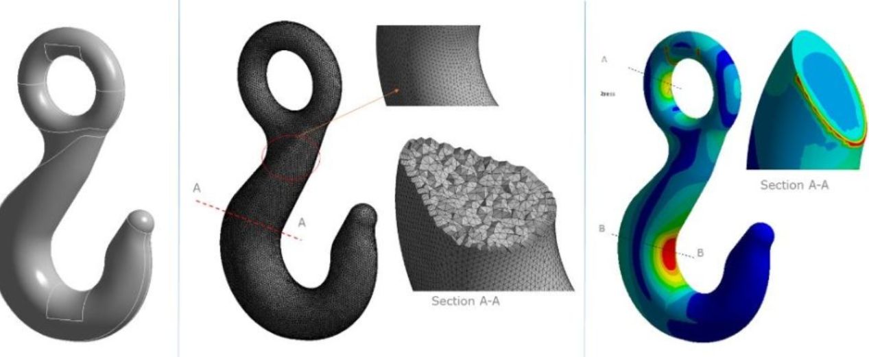
Structural Analysis is the most common FE analysis carried out. Characteristics such as mode shape, stress, deformation, fatigue life are the most common results processed. Shock loading analysis is another common analysis done to verify structural integrity. For composite material structures, FEM consists of microscale and macroscale analysis. In microscale FEM, analysis is done for individual materials. In macroscale FEM, the entire assemblage is analyzed for structural properties. Using FEM analysis, failure modes can be estimated. For composite material, the failure mode is different. Here, inter-laminar shear strength is a key material property.
In finite element analysis, the structure is discretized into smaller elements. The elements could be a 1D beam, 2D shell or plate and 3D brick or tetrahedral. Constitutive relation for material stress-strain is then formulated on the elements. This results in a large matrix, whose size depends on the degree of freedom for the selected element. A numerical sparse matrix solver is then employed for the solution. For some structures, meshes are created separately on each sub-component. The connections are then formed either using rigid links or by defining surface contacts. The common types are frictional and frictionless contacts. Non-linearity in FEM can arise from material or geometry. Both require solutions to be executed in sub-steps.
Case Studies
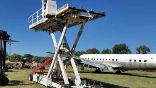
Conceptual Design of Ground Handling Equipment for Heavy Cargo Handling
The K-Loaders were required lift and load weight of up to 12 Tons from a height of 1m to 3m or more...
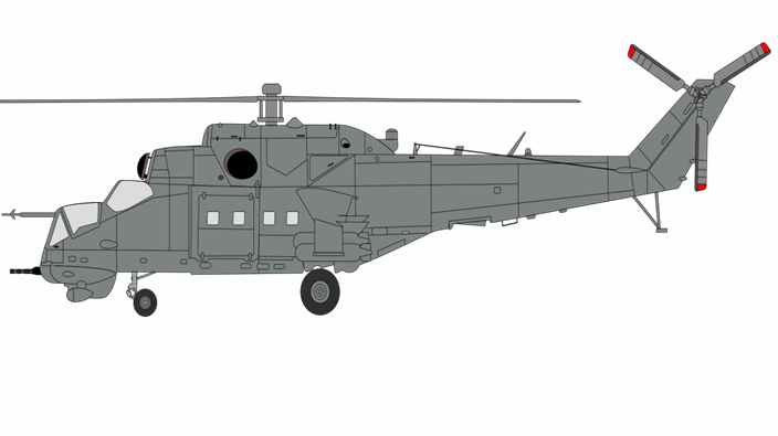
Structural Analysis of LRU Attachments on Military Helicopter
FEM analysis in Ansys® Mechanical against inertial loads in all the six directions. Modal Analysis...
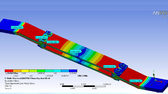
Structural Analysis of Sugar Dryer Assembly
Finite element analysis was carried out in ANSYS for the leaf spring, bottom plate and flange...